BOX JOINTS WITH ROUTER TABLE
I wanted to utilize box joints on a couple future
woodworking projects, of which I have never created box joints before.
Without re-inventing the wheel so to speak, I searched YouTube checking
out the various methods of making box joints and most were made using a
table saw and fixture, a router and a router table also with a jig.
There were a few products available, box joint jigs, but the reviews
were not that great; e.g., too much slop in the tracking mechanism or
slide.
I viewed a YouTube video product by Wood Magazine that I liked and they
offered an inexpensive set of plans with detailed drawings and
instructions for 3 bucks. I ordered the plans and completed the jig except for
routing for 3/8 inch width slot for the guide pin, since I did not have
a 3/8 inch diameter solid carbide router bit. As soon as the
router bit arrives, I will complete the set-up for the jig.
You can view the operation of the router table jig from Wood Magazine at this
link:
https://youtube/watch?v=G01hhn-kQnc.
and there is a direct hyperlink to the ordering
page.
I normally will do a detailed step by step construction of the jigs and
fixtures I make, however I will not do so on this one since it is
copyrighted and 3 bucks will not set you back unless you are kin to
Scrooge!
ROUTER JIG
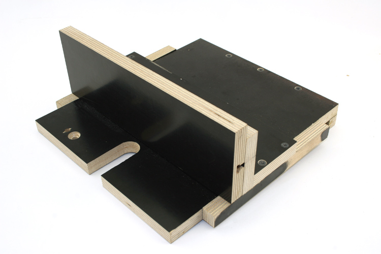
As noted above, I did not route for the guide pin in the
interchangeable fence which has a T-Slot. This jig is SN 382.
I used scrap aka unallocated phenolic laminated plywood to construct
the jig per the plans from Wood Magazine. I had to secure the
upper left portion of the base of the jig to my router table using a 1/4
inch x 20 tpi flat head bolt since the laminated material had a slight
warp or twist to it when I clamped the jig to my router table. The
jig base will stay in the same position each time it is used since the
1/4 inch x 20 tpi will locate it to the router table. The
above link to the YouTube video details the usage of said jig.
I will show the usage of this jig when I have it properly set up for
3/8 inch width box joints.
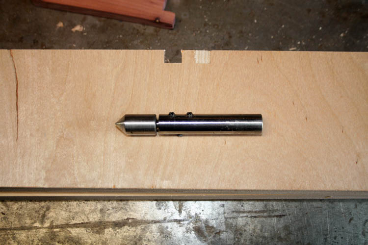
INSTALLED THE GUIDE PIN
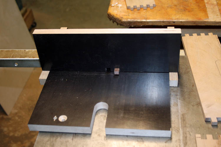
The guide pin was installed (glued in place) per instructions on the
YouTube video and time to give a test run on scrap wood.
MODIFIED THE JIG
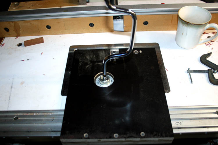
I modified the jig by cutting a 2 1/8 inch diameter hole in the base
plate where I have access to the router lift mechanism which makes it
easier to adjust the height of the router bit for the thickness of the
stock you are using.
Web page updated by Bill aka Mickey Porter on 02-10-2024.
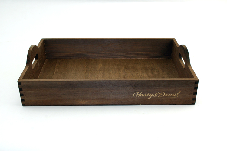
SERVING TRAY
We received a package from our son Bill, Jr. and Nichol, Vista, CA
shipped from Harry and David, LLC Medford, Oregon that had apples and pears including a
very nice wood serving tray. I decided to make a copy of the tray
and no use looking and experimenting with ideas and designs, definitely
not re-inventing the wheel again!
The bottom of the tray was a very thin piece of wood veneer glued in
place and decided to use some type of thin plywood between 1/8 inch and
3/16 inch thickness and route a groove for the bottom to fit into the
sides and end of the serving tray.
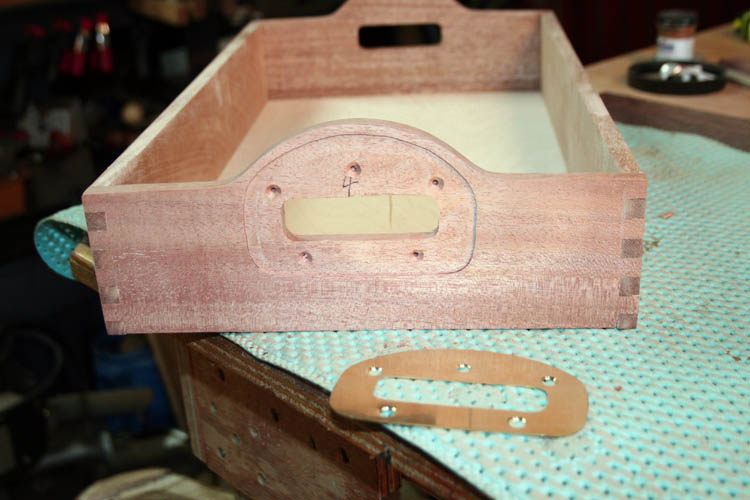
NOTE: The above serving tray does not have brass
inlaid handle reinforcements!
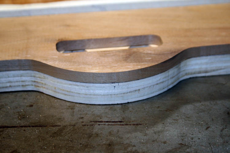
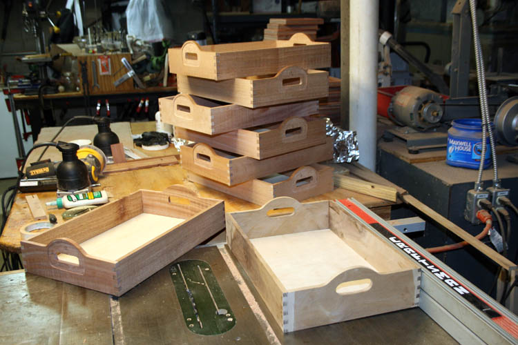
COMPLETED PROTOTYPE SERVING TRAY
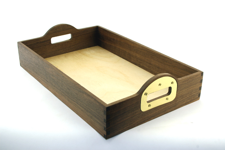
Above serving tray completed on 02-20-24. Length 17 1/4", Width
11 1/4", Height 3 inches at corners. The bottom panel is 16 5/8
length x 10 3/4 inches width x 1/8 inch thickness.
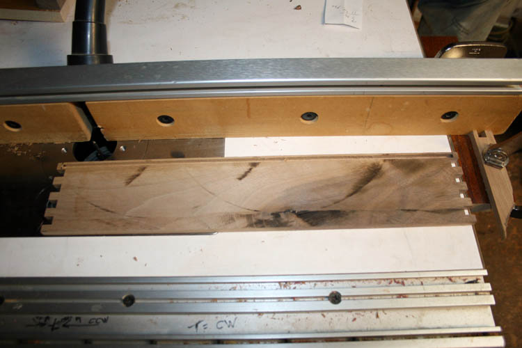
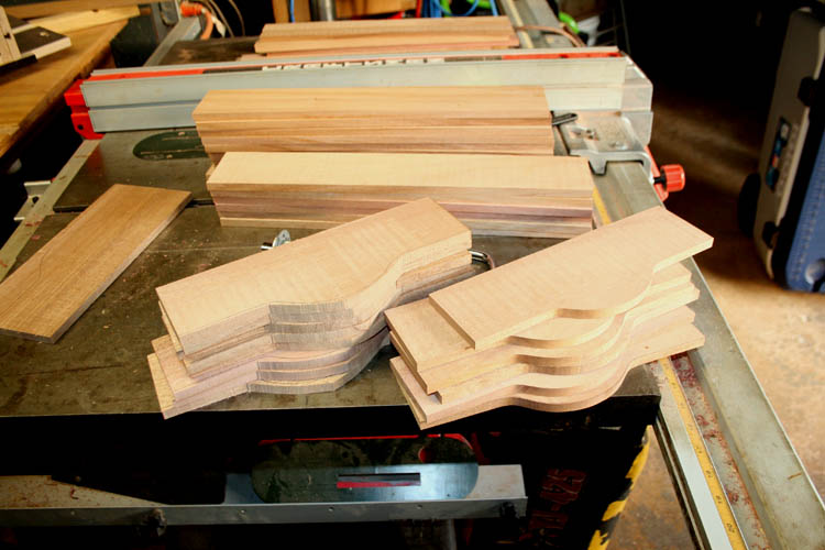
LETS GET STATED WITH A PROTOTYPE
I had a piece of 3/4 inch plus width of walnut and ripped it in
half using the table saw yielding two pieces 3/8 inch thick, however the
saw cut wasn't perfect, but will do for testing purposes.
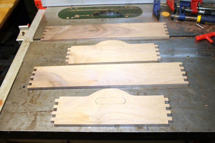
The four pieces above has box joints routed using the above jig and
will route a groove for the bottom using a scrap piece of 3/16 inch
thick Burch plywood. The box joints are slightly proud of the ends
to allow for final sanding.
ROUTED THE GROOVE FOR THE BOTTOM
There was not much room to spare with the slot and will reduce the
height of the next tray where there is a full width box joint at the
bottom of the boards. I believe I made this prototype about an
inch taller than the original serving tray. The slot is 5/32 inch
width.
The long sides of the tray has the slot stopped about half way in the
box joint from the end, otherwise you will see the bottom panel.
The router table had a stop installed at each end and the material had
to be lowered onto the spinning router bit, which can be dangerous if
not very careful.
This is the same technique used when putting a bottom in a tray
and/or napkin holder using dovetails.
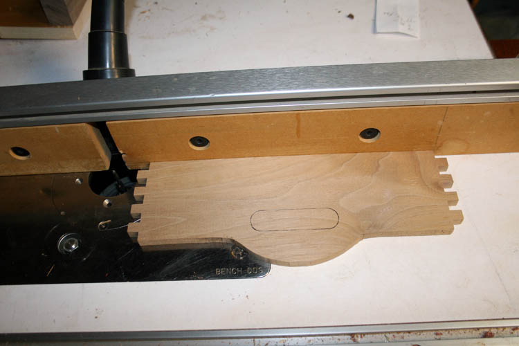
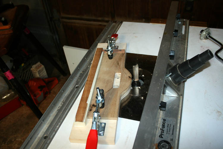
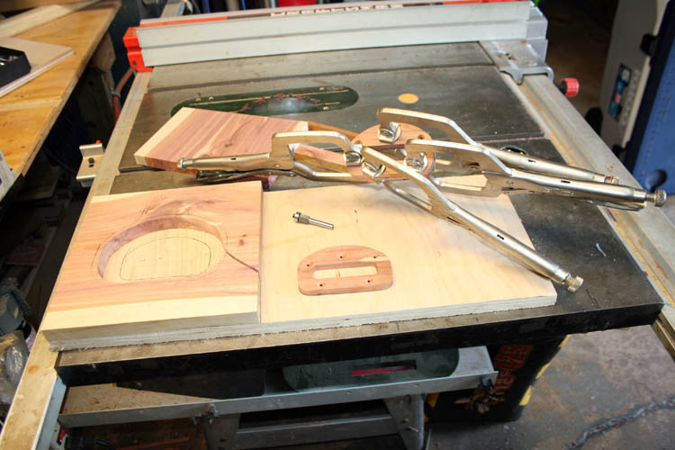
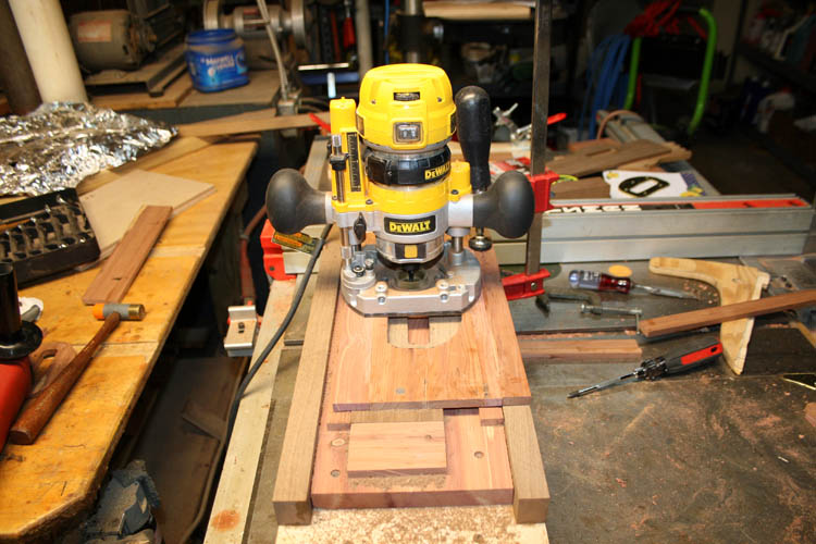
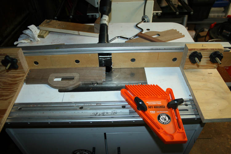
ROUTER JIG FOR TRAY END PIECES
I made a router jig for the table router to profile the ends of the
serving tray. The ends will be cut to length and the curvature rough cut using
the band saw to within an 1/8 inch of the profile and then placed on
this jig. A flush cut profile router bit will be used which has a
bearing that will
follow the curve of the profile pattern jig. To keep from any tear
out, the piece will first be routed starting at the center of the curve
and the jig will be moved into the router bit from the right to the
left. Once that cut is make, the piece will be flipped over and
re-clamped in the jig. Normally, you will feed the material to be
routed from the right to the left.
I used a pair of DeStaCo knock off clamps HH225D which to me works
better than the DeStaCo 225U clamps, plus they are a lot cheaper. This jig is SN 383.
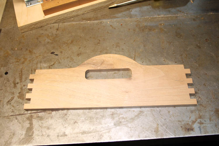
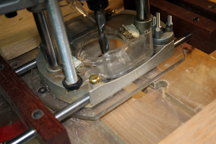
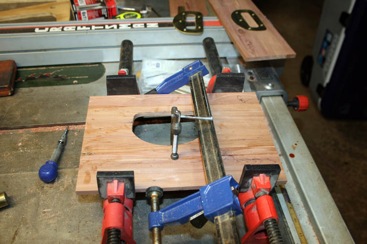
ROUTING THE HANDLE SLOT
I cut the slot in the test serving tray using a forstner drill bit at
each end and then used the jig saw to complete the cuts. However,
this is too slow and required additional sanding and will use a router
plunge bit the appropriate size and my
mortise fixture.
Above first prototype serving tray completed less glue up.
USING MY PAT WARNER DESIGN MORTISE FIXTURE
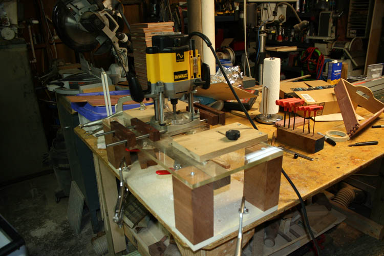
I didn't do any sequence pixs of cutting the handle holes in the ends of
the serving tray, but will show the
fixture and explain what I did.
The handle slots in the original serving tray were 13/16 inch width and
2 15/16 inch length. I did not have a router bit 13/16 inch in
diameter, therefore I used a 1/2 inch diameter spiral up cut plunge
router bit and
routed an appropriate opening for your fingers.
The mortise fixture will allow you to set the east to west limits needed and
also has stops for the North to South direction of the router. As
evidenced by the above pix, the mortise fixture and router does a
beautiful job requiring little if any sanding!
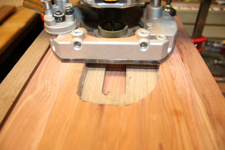
Close up of the mortise jig and router. The router can slide on
the 3/8 inch stainless steel rods left to right and have the stops set
to give me an approximate 13/16 inch width slot. The opening in
the Plexiglas top of the fixture is 3 inches wide by 6 3/4 inches length
which will allow for any mortise that I might need!
If you are making a mortise the same width as your router bit, you
tighten the two brass screws on the base of the router base which locks
the router in place onto the stainless steel guide rods.
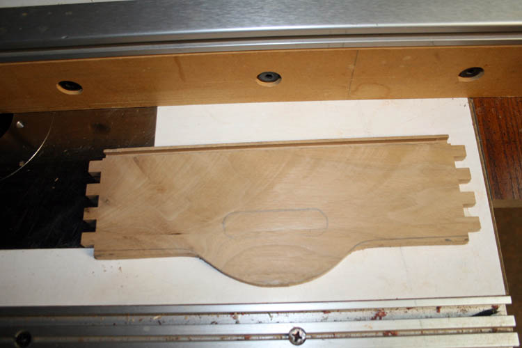
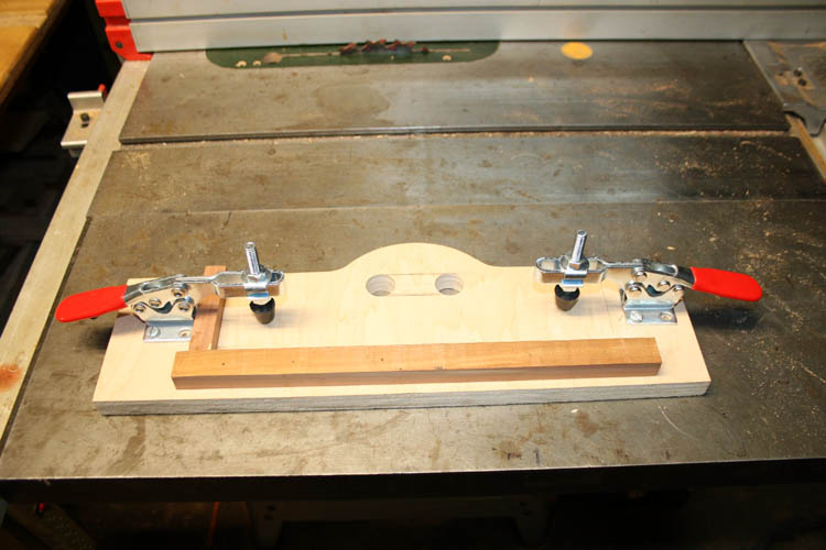
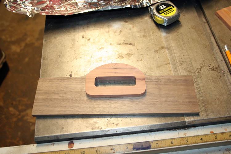
ROUTER JIG FOR END CURVATURE
I used scrap aka unallocated 3/4 inch birch plywood for the pattern
jig to cut the curvature of the handle ends of the serving tray. I
later added a piece of wood and several layers of masking tape to fine
tune it to the exact width that I needed. My goal for the box
joints was to have an equal width box joint at the top and bottom of the
sides, therefore the modification to this jig.
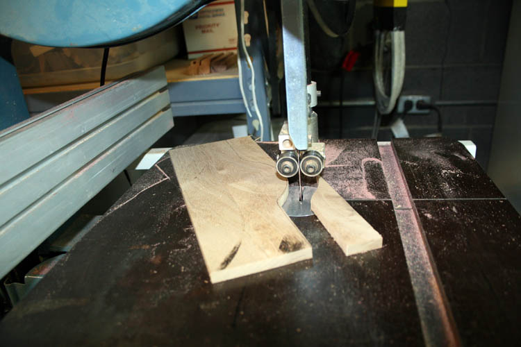
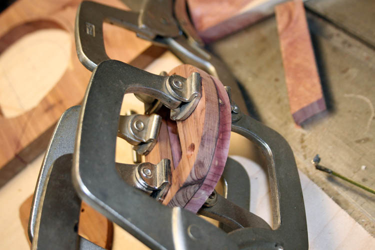
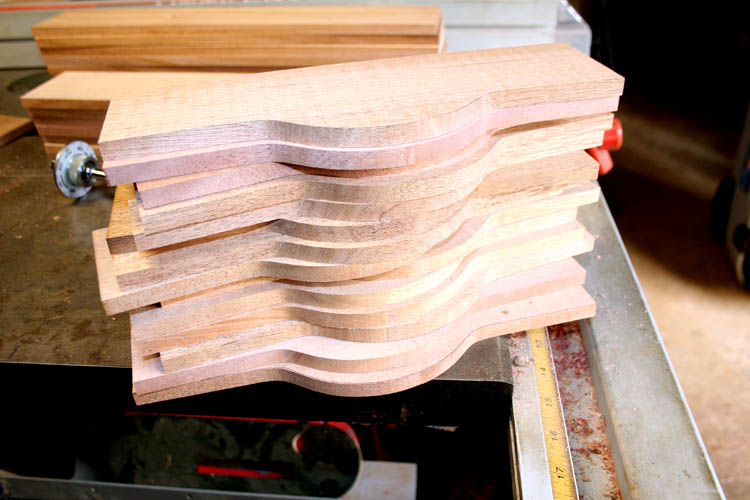
The end pieces were rough cut on the band saw to about 1/8 inches of
the line and then placed on the jig using a pattern bit that has a
bearing that follows the curvature of the pattern jig. The pattern
router bit I used was way too long and have one that is 1 inch in length
and will use that one when I set up to do a series of the serving tray.
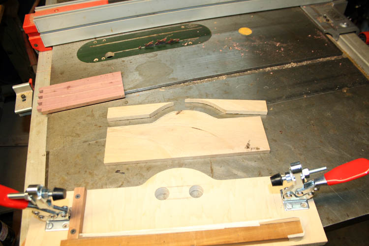
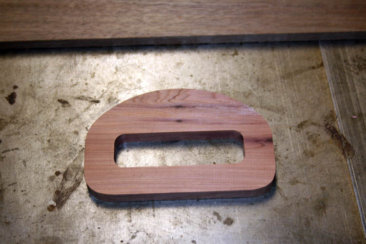
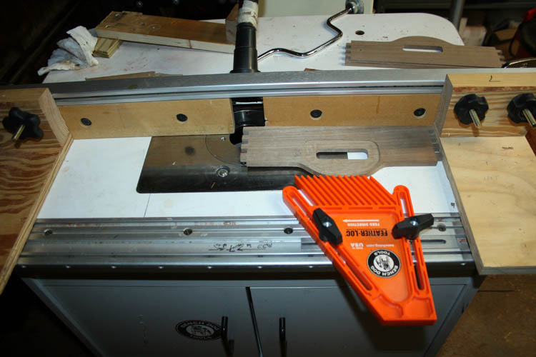
End pieces ready to route the curve of the handle.
Ready to route the end pieces.

The pattern fixture aka jig leaves a good finish cut to the curvature
requiring very little if any sanding. I later went back and sanded
the edges of the pattern jig to remove most of the band saw marks left.
I will show the glue up of the serving tray later and will round up
some lumber and plywood for the bottom. I plan to add a thin brass
insert for each handle to give it additional strength, but will no doubt
free hand the route.
JIG FOR ROUTING .025 BRASS
I am planning on building at lest six (6) or more of the serving
trays, therefore I am thinking about routing the thin .025 inch
thickness brass using my DeWalt 625 3 HP variable speed router using a
pattern and a flush cut pattern router bit. I have never routed
brass or aluminum in the past, however I have used a scroll saw and
jewelers saw blade to cut .062 inch brass which was very laborious to
say the least and have stamped brass using a punch press and die set.
Here is an example:
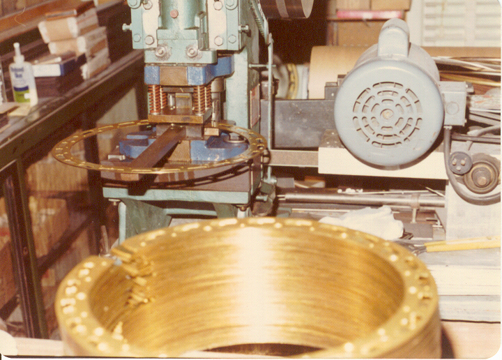
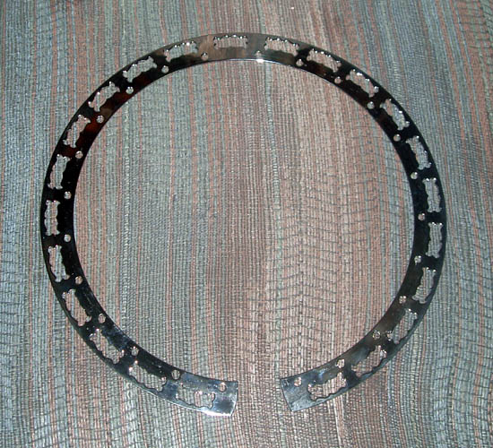
Below is pix of example where I cut the tone holes in the nickel
plated brass using the scroll saw and jewelers saw blades:
I did some research via YouTube and the internet how to cut brass
using a router and it appears to be doable for sure.
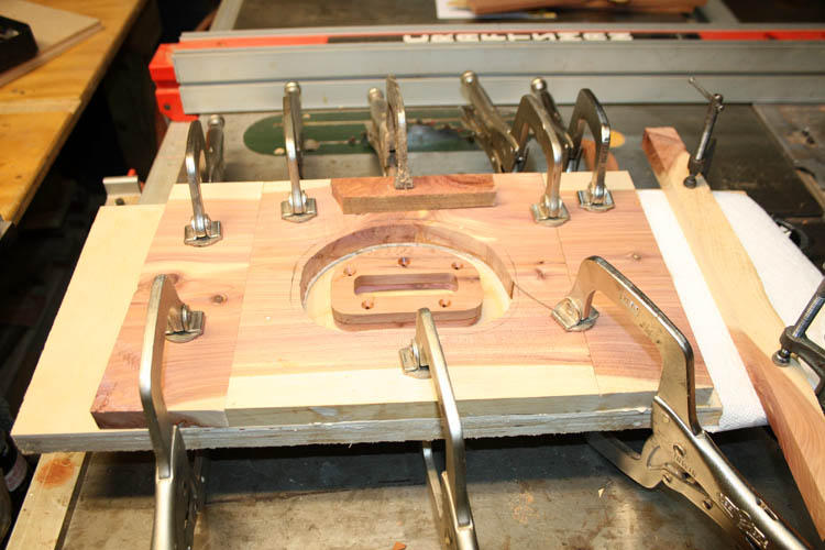
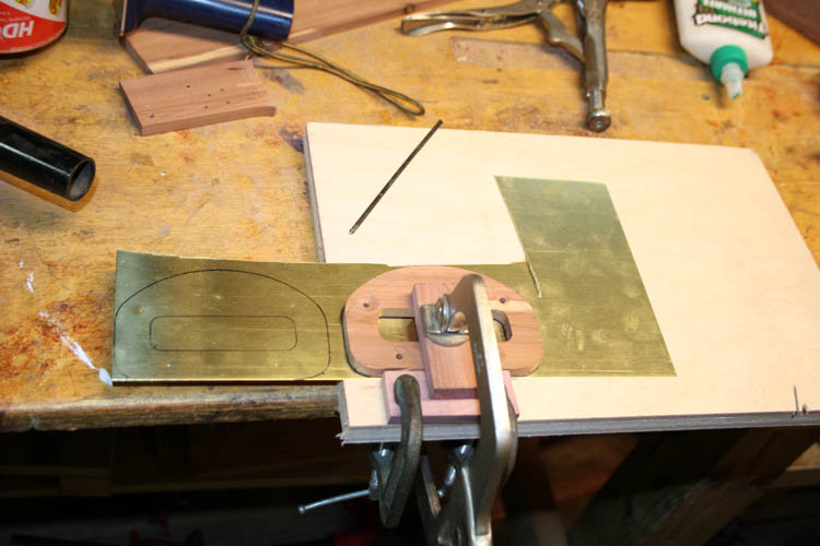
FIXTURE/JIG CONSTRUCTION
I first made an exact wood pattern: one for marking the brass and the
other for the wood pattern to use with the router and a flush cut
pattern router bit.
There will be about 3/16 inch width inside the outer edge (curvature)
of the handle area and the wood pattern was cut to size using the band
saw, table saw, miter saw and final sanding to the edge of the line
traced onto the wood. The center portion was cut out using my Pat
Warner design mortise fixture first while the wood was full length.
Five (5) small countersinked holes were drilled into the pattern for
attaching the brass plate.
Scrap wood was used to fabricate the fixture/jig and above pix the
first stage to make the base plate.
I glued a double layer of the pattern so the bottom of the pattern
flush cut router bit would have clearance since it has a nut on the base
to hold the bear and the carbide cutter in to the shaft of the router
bit.
I rounded up addition scrap wood to extend the length of the
fixture/jig to give plenty of real estate for the large router base.
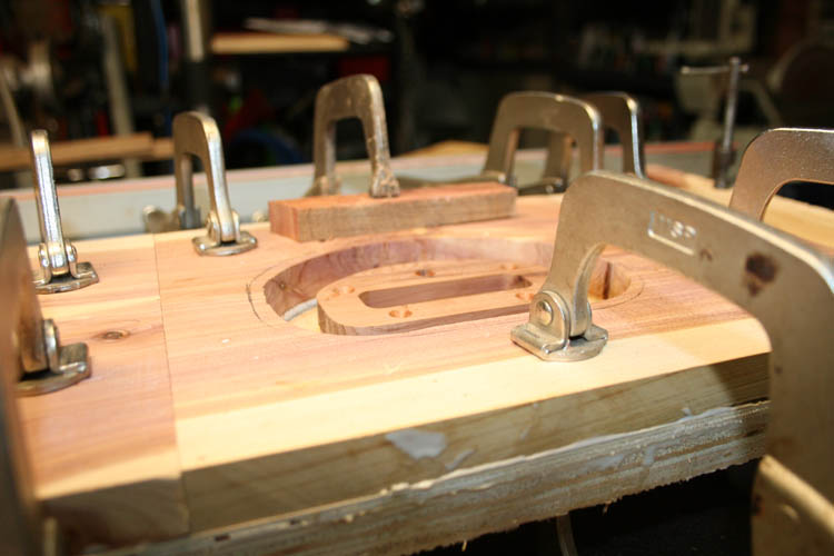
From this angle (view) you can see the actual pattern is below the
surface of the top base plate to allow for stacking several pieces on
brass to the pattern using flat head screws.
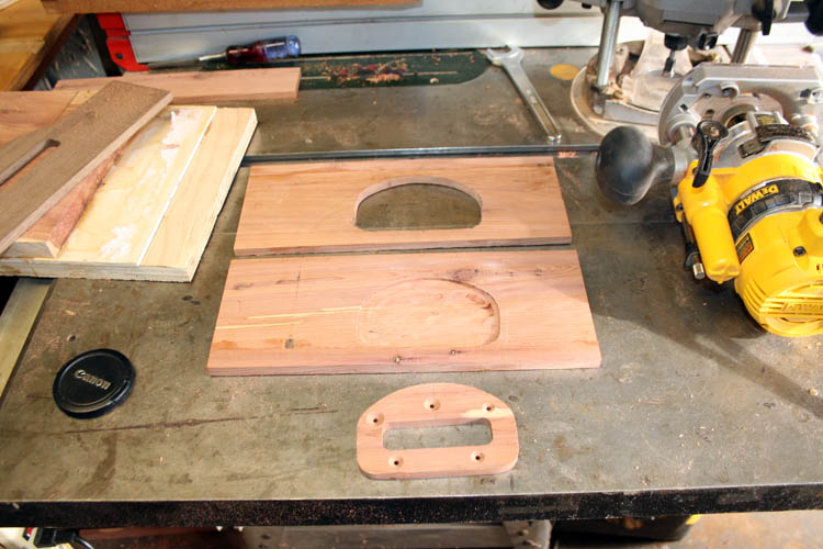
To use the fixture/jig, the brass will first be marked and drilled
using the pattern marking plate. A hole drilled in the center
portion to allow for threading a jig saw blade and cutting the inside
portion where you fingers will go and then cut the outside shape
slightly oversize of the pattern jig. The brass plates will then
be screw to the pattern and routed using the DeWalt 625 variable speed
router with reduced speed around 12K RPM using a flush cut pattern
router bit. This jig is SN 384.
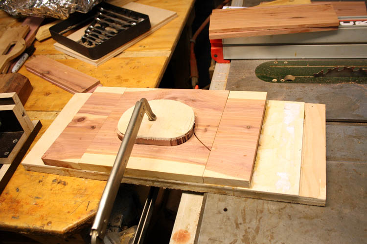
Above with the pattern glued in place to the fixture jig.
There was a good amount of time to make the fixture/jig up to this
point and I certainly do hope it works as intended, grin if you must!
Otherwise, the brass plates will be cut free hand on the scroll saw!
NOTE: After cutting out the brass handle insert with the
scroll saw and a # 6 jewelers saw blade, I decided not to use the above
router jig for the brass.
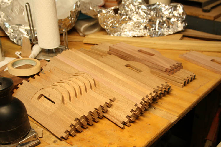
ROUTER PATTERN JIG FOR THE CUT OUT IN THE HANDLE
If the above jig works ok, I will fabricate a router jig using a
guide bushing to inlay the brass insert into the handle of the serving
tray.
Above is part of the jig making process to route the cut out for the
handle brass insert. The top is a pattern cut, of which I started
to make the cut on the band saw, but switched over to the scroll saw
using a jewelers saw blade. The next portion is the actual route
in a test piece of wood which I had to fine tune the upper jig a few
times to get the bottom pattern to fit in the routed portion.
In essence, I used a small DeWalt router with a 3/8 inch outside
diameter guide bushing with a 1/4 inch solid carbide up cut router bit
which means I had to increase the lower pattern size .062 inches all
around. I marked around the lower pattern with a Sharpie marker
and had a thin piece of wood between the pattern and the marker to give
me an approximate .062 inch clearance or increase in the pattern.
Again, it was very laborious; e.g., trial and error. With CNC,
this would be a piece of cake, but have to use what is available in my
woodworking shop.
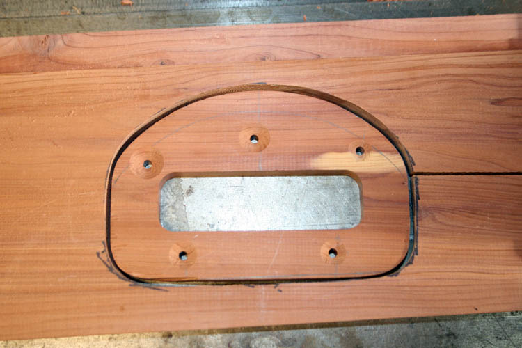
A pix of the pattern inside the jig cut out for the router. It
is not perfect, but close enough! I later glued a small piece of
wood to fill in the gap left by the band saw blade to keep the wood from
opening up any further.
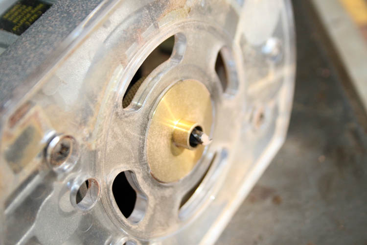
Pix showing the router guide bushing with the exposed 1/4 inch
diameter router bit. The guide bushing will follow the inside cut
out of the wood pattern. As stated, there is .125 inch total
difference between the outside diameter of the guide bushing which is
.375 inches and the .250 inch diameter router bit., which equates to
.0625 inches all around the pattern desired.
A jig to position the end tray member to be pattern routed. I
am figuring this jig out as I go and will no doubt mount this jig onto a
larger piece of Burch plywood to give the small router base more real
estate to work with.
The router pattern will need to be precisely located in position on
top of the serving tray handle end.
BRASS HANDLE INSERT CONSTRUCTION
I "changed horses in the middle of the
stream", so to speak and after cutting one of the brass
plates out with the scroll saw using a # 6 jewelers saw blade, I could
cut freehand to the pattern close enough without having to use the
router jig made for the brass.
In the past, I cut mother of pearl and abalone musical instrument
inlay patterns
and was very accurate with the scroll saw. After cutting the above
brass handle insert, years of experience quickly came back and no need
to route the outside profile of the brass insert.
After cutting a couple of the inserts out, the light bulb came on and
I decided to rough cut the outside profile from the sheet brass which is
6 x 12 inches x .025 inches using my Milwaukee 4.5 inch angle head
grinder with a thin friction cut off wheel which cut the thin brass
easily.
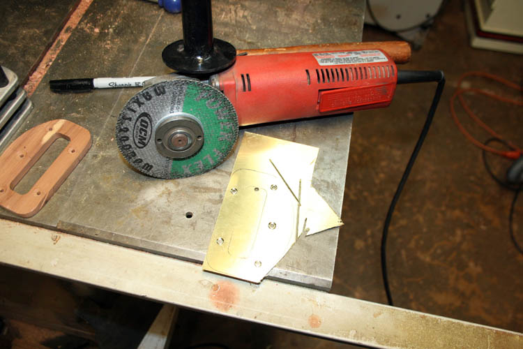
I first marked the pattern onto the brass using a extra fine Sharpie
marker, then used a 1/8 inch diameter center transfer punch and marked
the screw holes. I then went to the small drill press and used a
120 degree countersink bit for the screw holes. I then drilled a
1/8 inch diameter hole inside the cut out where your fingers will go on
the brass/serving tray handle to thread the jewelers saw blade to
complete the cut out.
After the center finger hole was cut out, I then took the brass
handle insert to the 6 x 48 inch belt sander and sanded the outside
diameter to the line marked. This was
"working smarter, not harder" in my humble opinion. I
checked the fit with a test route piece of material.
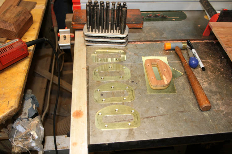
I was able to get five (5) brass handle inserts from one piece of the
6 x 12 inch .025 inch sheet brass.
I am thinking about building six (6) of the serving trays for family
and one for our neighbors.
On Monday, our Lord willing of course, I will complete the router jig
for the handle brass insert. There is not much room for error in
this jig since the routing jig has to be precisely aligned over the top
of the serving tray handle end which already has the cut out for your
fingers routed into the wood piece. I increased the width of the
router jig pattern and mounted the base to a piece of birch plywood to
give more real estate for the router which has the guide bushing and the
1/4 inch diameter up cut solid carbide flat bottom router bit.
ROUTER JIG PATTERN FOR CUT OUT CONTINUED
In the above pix, I have glued additional side material to the router
profile pattern cut out jig which hopefully will allow me to position
the above jig on top (pattern plate) of the base plate that
positions/holds the serving tray ends in place. I will trim the
sides to the desired width.
I also glued in additional strips of wood on the sides of the jig
that is flush aka level with the serving tray end piece that will
contain the brass inlay handle reinforcement that will strengthen the
handle area. I have marked where the brass inlay will be
positioned once routed out.
I screwed a piece of 4 x 4 scrap wood to each end of the above
fixture/jig to elevate the jig off the table and/or circular saw table
where I will clamp the fixture down.
I will have to figure out a hold down method to keep the top router
pattern in place and do have enough material on each side for alignment
pins. I will probably glue a couple more filler strips of wood the
same height as the serving tray end piece to keep it from moving; East
to West. The North to South portion is secured in place with end
stops with a few thousands of an inch clearance.
ROUTER PATTERN PROFILE JIG COMPLETED
The pattern profile was fixed into position over the serving tray end
piece using # 6 drywall screws 1 1/8 inch in length. I used a
tapered pilot and countersink hole drill and drilled in several places
on the outside of the pattern profile to keep the pattern profile jig in
place and flat to the piece to be routed. This jig was more or
less "fly by the seat of your pants"
and figured it out as I went!
There is plenty of real estate surface for the small router to move
on with the additional "wings" added to the original pattern profile jig
I made earlier.
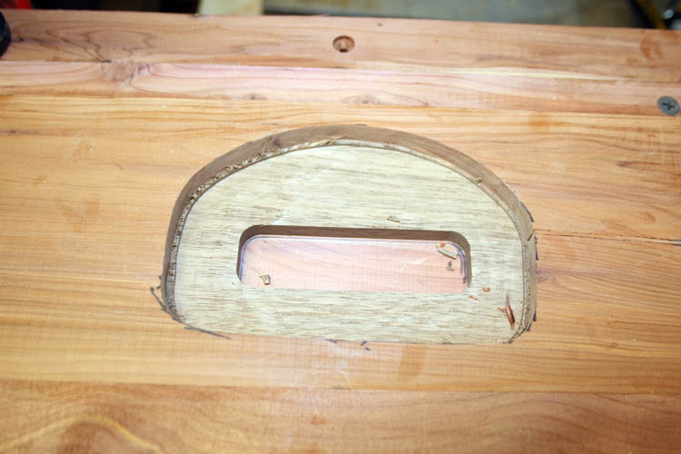
The serving tray end piece is routed for handle brass insert. I
used a chisel to clean the top edges of the piece routed.
This pattern profile router jig is not perfect, but not too shabby
for making the jig freehand without the benefit of a CNC machine.
I am sure there are better ways to construct the profile jig using
intermediate profile jigs using the master pattern to locate from.
This jig is SN 385.
NOTE: I definitely made the router profile pattern jig
the hard way since Whiteside offers a router inlay kit # 9500 which
allows you to make a profile pattern jig using a template, which in my
case would be the wood master pattern used to cut the brass inlay and
you then make a template using their router bushing(s). In the
future, I will purchase the inlay kit for my next inlay project!
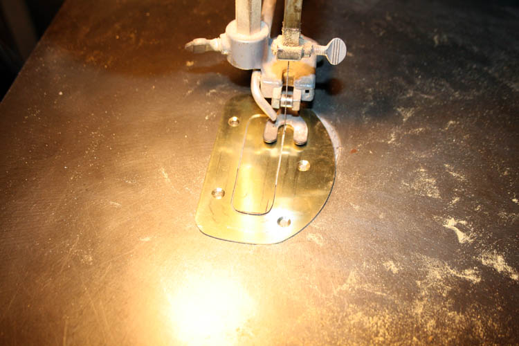
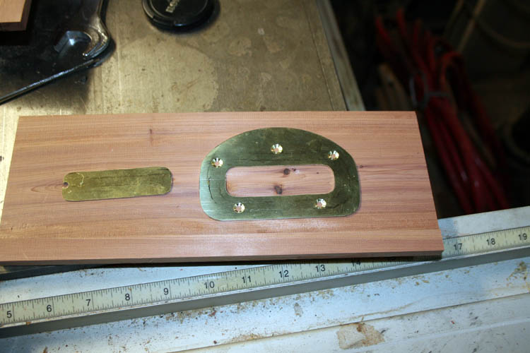
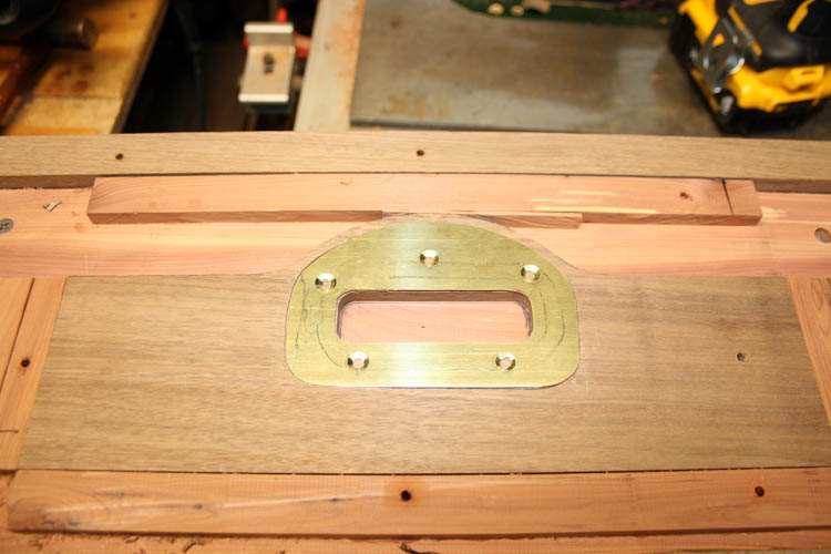
INSTALLING BRASS HANDLE REINFORCEMENT
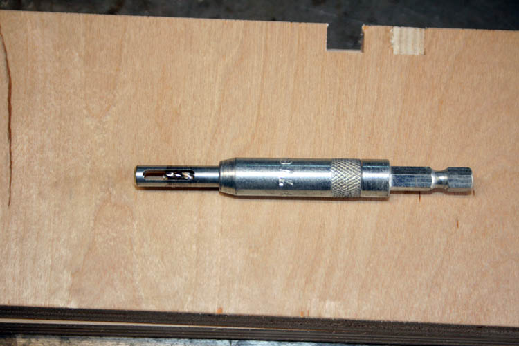
The brass insert was placed into the cavity excavated aka routed out
and then used a 7/64 inch spring loaded self-centering drill guide, pix
below which works for # 6 wood screws:
I then used a 80 degree tapered countersink drill bit to account for
the taper of the flat head screws, pix below:
I will route the box joints in the end pieces and side of the serving
tray and then route a 5/32 inch width groove in the bottom of the
members for the 1/8 inch thick Birch plywood panel aka bottom.
ROUTING GROOVE FOR THE BOTTOM OF SERVING TRAY
Above stops that control the length of the groove in the handle ends
of the serving tray. As stated earlier, you have to lower the end
piece onto the spinning router bit which can be dangerous destroying
your end piece and could hurt yourself.
Alternate method would use a router on top of the end piece, but you
could easily ruin the piece since there is little margin of error
between the groove which is 5/32 inch width and only 3/8 inch width of
the box joint.
No stops were needed for the sides of the serving tray.
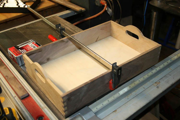
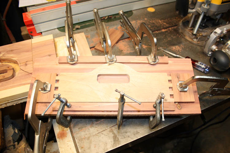
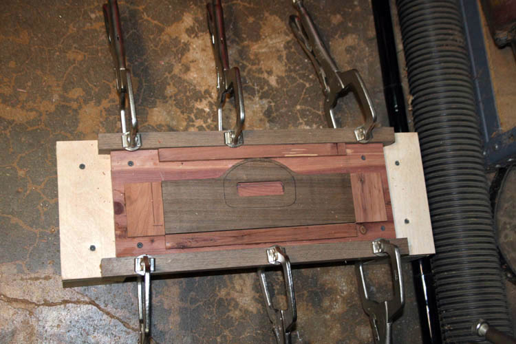
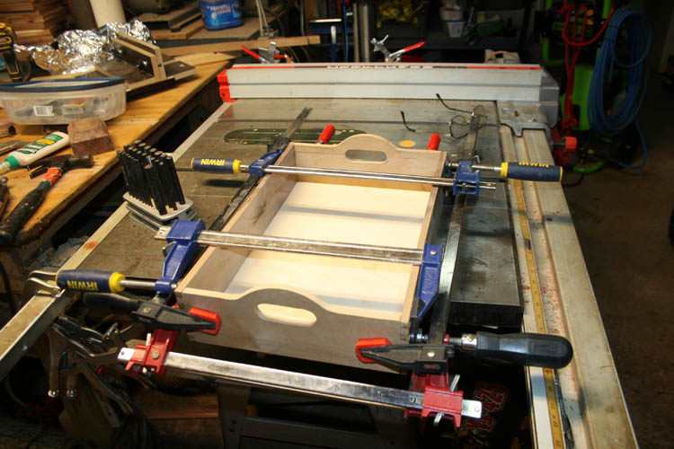
GLUED THE SERVING TRAY TOGETHER
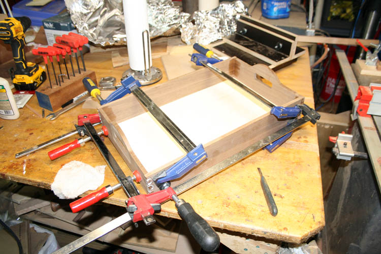
With making only maybe seven (7) +- serving trays, I will not make a
glue-up fixture just for the serving trays, but will use clamps as
above.
One of two serving trays without a brass insert which were my test
trays!
TO COMPLETE THE SERVING TRAY
The serving tray box joints will be sanded flush when glue is dried
overnight, final sanding and inserting and screwing in place the brass
handle inserts. When the weather permits, a few coats of musical
instrument grade lacquer will be sprayed onto the serving tray.
I have an adjustable # 6 drill centering bit to drill pilot holes
into the ends of the serving tray to secure the brass inserts.
When using pattern profile jigs and fixtures, it is imperative that
all your parts to be milled/profiled be as accurate as possible to locate to the jig for
repeatability.
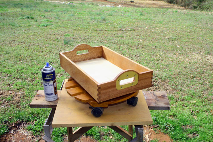
FINISHED PROTOTYPE SERVING TRAY
I sanded the serving tray and installed the handle brass inserts and
then sprayed a couple coats of lacquer on the serving tray. This
prototype serving tray will be SN 386. I have two other test
serving trays to complete which will not have the brass inserts.
I am well pleased with the serving tray. I decided not to stain
the Baltic Burch plywood bottom and I like the contrast between the two
woods. I have mahogany wood ordered to complete additional serving
trays for family members and our closest neighbor, our Lord willing of
course.
STARTED EIGHT ADDITIONAL SERVING TRAYS
I received the mahogany wood ordered and got the ends and sides cut
to dimensions along with cutting the curved portion of the serving tray
end pieces.
Today being 02-23-2024, I started routing the cavity out for the
handle brass inserts. I reworked my router jig by adding
additional shims glued to the sides for a flush fit of the end piece to
prevent torking the upper router profile pattern.
As stated earlier, the end pieces are marked from the profile pattern
and band sawed close to the line and then clamped onto the router
profile jig and using the router table.
The profile router table jig for the handle curve saves a bunch of
time and sanding in my humble opinion.
I was short brass for the handle inserts and ordered a 6 x 12 x .025
inch piece which will give me five (5) units.
PROJECT MOVING ALONG
I glued up two serving trays today (02-26-2024) and test fit the other
six (6) units. I had four end pieces that had the box joints in
the wrong orientation, (my bad) and cut the box joints off and routed
them again which shortened the width of two of the serving trays
approximately one inch. The box joints on a couple were
"tight as two coats of paint", because I didn't have enough scrap aka unallocated material to adjust
the box joint jig to fine tune it properly.
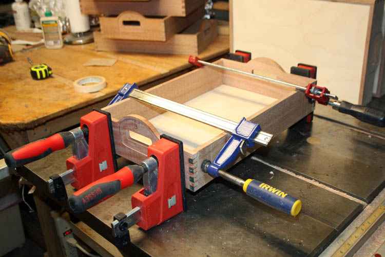
The above Bessey parallel clamps bar clamps worked good for this project.
I used them on my
custom keepsake boxes, but did not like
them. The Merle band clamps worked much better keeping things at a
right angle.
I sprayed a couple coats of musical grade instrument lacquer on the
serving tray that did not have handle brass inserts (test serving tray).
I will get into my cruise control mode aka retirement mode and glue
up one serving tray each day and do a final sanding on it and install
the brass inserts into the handle ends. When the weather permits,
I will then apply a couple coats of musical grade instrument grade lacquer.
Cutting the brass handle inserts was the most time consuming and
challenging part of this project.
FINAL SERVING TRAY COMPLETED
I sprayed a couple coats of Deft lacquer on the last serving tray
completed. It rained a day or two and put the project on hold
until today.
This has been another fun woodworking project and I am going to
insert a table of the cost for the 10 serving trays that have the brass
handle reinforcements. I did a couple test serving trays without
brass inserts using scrap aka unallocated wood.
SERVING TRAYS COST